-40%
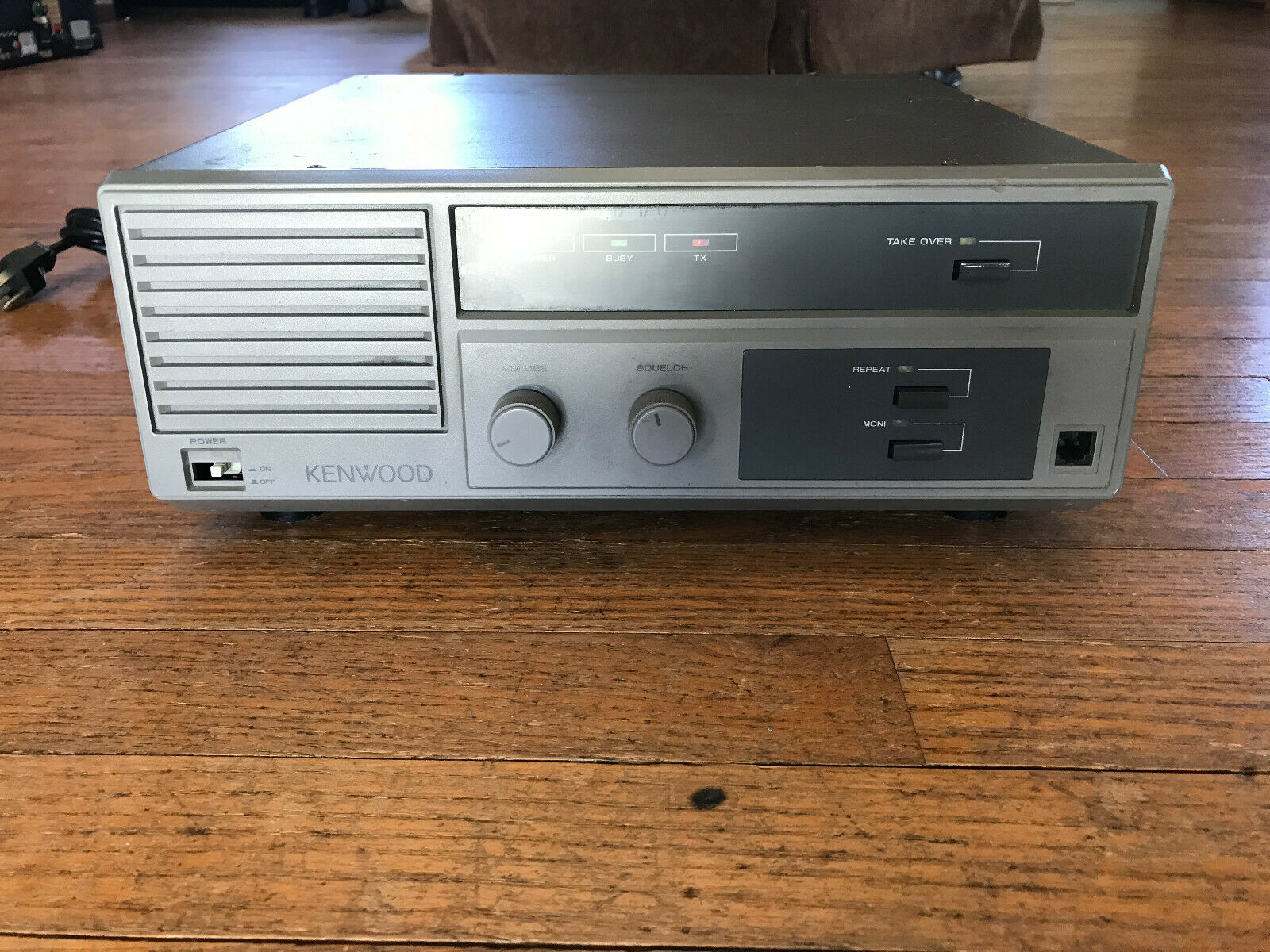
Frequency and PL Programming for KENWOOD TKR-820 Repeater
$ 17.42
- Description
- Size Guide
Description
THIS DOES NOT INCLUDE A REPEATER! It is programming for a repeater.What I need you to include when you checkout in the Paypal note is this:
TX Frequency
RX Frequency
RX PL frequency (Up to 8 Different)
TX PL frequency (Up to 8 Different, each TX frequency must have an RX frequency)
I only do tone PL frequencies, not DPL
IF YOU DON'T INCLUDE THIS EXACT INFORMATION ABOVE, IT WILL DELAY YOUR ORDER, WHILE I TRY TO FIGURE OUT WHAT YOU MEANT!
What you will receive is two DIP chips and a socket.. You must already have a TKR-820. I send you the pre-programmed chips and you do the labor to change them out. For the PL Frequencies, the chip is in an IC Socket, so it is easy to change. For the frequency, you will need to de-solder the existing chip on the front panel board, and then install the included socket and then plug the IC in. You MUST have de-soldering experience to purchase this. If you do not have de-solder experience do not buy this!
So for the money, you get 2 EPROMS programmed and instructions here
You can download the service manual at repeater-builder.
Process to change the chips I send:
1. Remove the top and bottom covers (4 screws each cover)
2. Remove the two front knobs.
3. Place the repeater on its side and gently pry each of the 6 plastic tabs, 3 on the top, 3 on the bottom that are (See picture 2 above) holding the front cover on, then remove the front cover, taking care to not lose the three buttons that protrude through the front. Remove them and place aside.
4. Remove the nut and washer from the squelch and volume controls. (See picture 3 and 4 above)
5. Remove the two top screws, one on each side of the repeater (see picture 5 above), lift up and tilt front panel down.
6. Remove all the cables from the main front board, and then the 5 screws holding it and remove board. (see picture 6 and 7 above)
7. Using your favorite de-soldering method, remove the chip in the picture 8 and 9. Make sure you clean any flux off the board.
8. Solder the socket in, making sure you have the correct orientation (picture 10)
9. Insert the chip marked "F" into the socket (picture 11). This is the frequencies chip.
10. Reassemble what you have disassembled to this point.
11. Replace the chip circled on the signaling board in picture 12 with the chip marked "P". This is the PL Chip. Make sure you have the correct orientation.
So you get 2 chips and 1 socket. You don't have to send your repeater back for me to program it this way (paying shipping both ways). This is less than 1/2 the total cost of shipping!
What I need in your checkout in Paypal is for you to include the following:
TX Frequency
RX Frequency
RX PL frequency (Up to 8 Different)
TX PL frequency (Up to 8 Different)
IF YOU DON'T INCLUDE THIS EXACT INFORMATION ABOVE, IT WILL DELAY YOUR ORDER, WHILE I TRY TO FIGURE OUT WHAT YOU MEANT!
Please feel free to ask questions! Once you have made the conversion, you can easily change frequencies just by swapping chips!
Please check our feedback and buy with confidence!
Two for the price of one. Both have 180 second record capacity, they have been tested and are working.
Please feel free to ask questions.
